
主要内容:
In order to prevent overcharging of lithium-ion batteries, lithium-ion batteries must be designed with protection circuits, and lithium-ion battery protector ICs are suitable for single-cell and 2~4-cell battery packs. The requirements of the protector are introduced here, and the circuit protector of the single-cell lithium-ion battery circuit is also introduced.
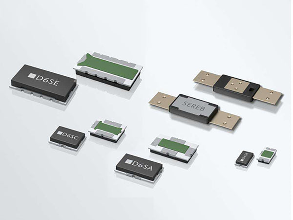 Lithium-ion battery protector
锂离子电池保护器的基本要求如下:
①充电时必须充满电,终止充电电压的精度要求在±1%左右;
②充放电时无电流,应设计短路保护;
③达到放电终止电压时禁止继续放电,放电终止电压精度控制在±3%左右;
④在充电前用小电流对深度放电的电池(不低于放电终止电压)进行预充电;
⑤为保证电池稳定可靠工作,防止瞬态电压变化的干扰,内部延时电路应设计过充、过放、过流保护,防止瞬态干扰引起不稳定;
⑥ 节省电能消耗(充放电时应给保护器通电)。单节电池保护器的功耗一般小于10μA,多节电池组一般在20μA左右;当到达放电终止时,处于关断状态,一般消耗小于24μA;
⑦该保护器线路简单,外围元器件少,占用空间小。一般可制成电池或电池组;
⑧保护器价格低。
1、单节锂离子电池保护器
下面以AIC1811单节锂离子电池保护器为例,说明该保护器的电路及工作原理。
该装置的主要特点是:终止充电电压为4.35V、4.30V和4.25V(以型号A、B、C为代表),充电电压精度为±30mV(±0.7%)。工作电压为3.5V时,工作电流为7μA,放电终止后功耗仅为0.2μA;有过充、过放、过流保护和延迟以避免瞬态干扰;过放电压2.4V,精度±3.5%;工作温度 ̄20~+80℃。
在正常充电和放电过程中,V 1 and V2 are turned on. The charging current flows in from the cathode (+), charges the battery through the fuse, and flows out from the anode (-) after passing through V1 and V2. During normal discharge, the current flows from the + terminal through the load RL (not shown in Figure 1), through one terminal and V2, V1 to the negative electrode of the battery, and the direction of the current is opposite to the direction of the charging current. Since the on-resistance of V1 and V2 is extremely small, the loss is small. Refer to Figure 2 and Figure 3 for the working status of several protection circuits.
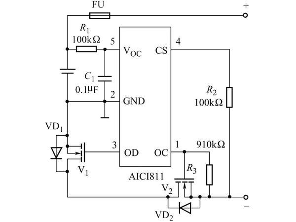 Figure 1 Schematic diagram of a single-cell lithium-ion battery protector circuit
(1) 过充电保护
如图2所示,P 1是一个控制过充电的带迟滞的比较器。由R 6和R 7组成的分压器连接到锂离子电池的两端。中间检测电池的电压接R 1的同相端,P 1的反相端接1.2V基准电压。充电时,当电池电压低于过充阈值电压时, P 1反相端电压大于同相端电压,P 1输出低电平导通Q 1,偏置电阻RV2 的3有电流流过,使 V 2也导通。导通(充电时V 1导通),从而形成充电回路。当充电达到并超过充电阈值电压时, P 1同相端电压超过1.2V,P 1输出高电平。延时100ms后,Q 1截止,R 3无电压截止V 2,充电电路断开,防止过充。
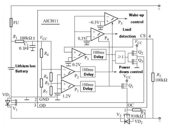 图2 几种保护电路工作状态示意图
(2)过放保护过放
保护电路由R 4和R 5组成的分压器、带迟滞的比较器P 2 、100ms延时电路、或门和Q组成的CMOS输出电路组成2和问题3。当电池放电到2.4V时,P 2输出高电平,延时后OD输出低电平,V 1截止,放电电路断开,禁止放电。
(3) 过流保护
Taking the discharge current overcurrent protection as an example, the CS terminal is the discharge current detection terminal, which continuously detects the discharge current. This is because the voltage VCS at the CS terminal has a certain relationship with the discharge current IL, as shown in Figure 3. If the on-state V1 and V2 are regarded as a resistor, the discharge circuit is shown in Figure 3.
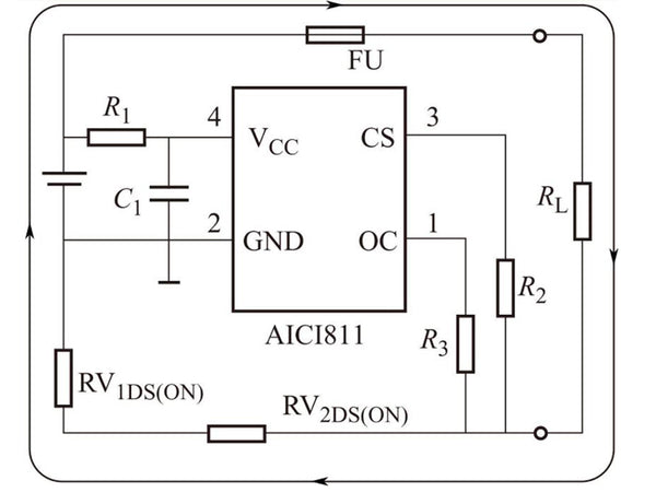
Figure 3 Single-cell lithium-ion battery overcurrent protection
The overcurrent protection circuit is composed of a comparator P3, a delay circuit or gate and so on. If the discharge current exceeds the set threshold and VCS exceeds 0.2V, P3 outputs a high level, and the result is the same as the over-discharge situation, which turns off V2 and prohibits discharging. Other functions of the device will not be introduced here.
2. Protection of 3~4 lithium-ion batteries
现以MAX1894/MAX1924为例说明其功能和特点。MAX1894 设计用于 4 节锂离子电池组,而 MAX1924 适用于 3 节或 4 节电池组。两个保护器可以监控串联电池中每节电池的电压,避免过充过放,有效延长电池寿命。此外,它还可以防止充电和放电过程中电流过大或短路。
两个器件组成的保护器电路如图4所示,是4节锂离子电池组的保护器。串联的四节电池在充电时电压基本相同(均压),故在内部电路和外加电阻、电容等元器件;此外,它由微控制器(μC)控制,可以输出电池状态信号,使功能更加完善。
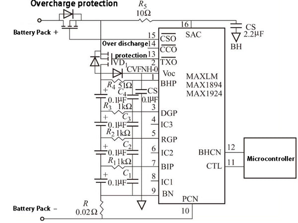
图4 两个器件组成的保护电路原理图
两款器件的主要特点是:每节电池的过压阈值均可设置,电压精度可达±0.5%;终止放电电压阈值也可设置,精度可达±2%;有关机模式,关机状态下每小时功耗0.8μA,可以防止电池深度放电;典型工作电流为30μA;工作温度范围为-40~+85℃。
联系人:余工
手 机:198-5307-5821
邮 箱:batteryltd@sina.com